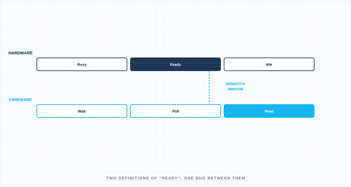
A specific category of integration bug shows up again and again across power electronics programs, and it has a specific shape: hardware and software each behave exactly as their own designer intended, and the combination still fails, because the two designers were reasoning about slightly different definitions of the same event. "The ADC conversion is complete." "The gate driver fault has cleared." "The communication peripheral is ready to transmit." Each of these sounds like an unambiguous hardware state — and each one is, in practice, defined by a specific register bit, a specific timing window, and a specific set of preconditions that hardware and software can silently nterface-bugs.svg)
The gap between "the datasheet says" and "the actual silicon does"
Component datasheets specify timing parameters — setup time, propagation delay, ready-flag assertion timing — as guaranteed bounds, usually with margin. Firmware written strictly against the datasheet's stated timing is technically correct and can still fail intermittently if the actual timing behavior of the specific silicon revision in use sits closer to the boundary than the nominal datasheet value suggests, especially across temperature and voltage corners the original bring-up testing didn't fully explore. This is why a communication or conversion routine that works reliably on an engineering sample can show intermittent failures on a production unit pulled from a different wafer lot or a different point in a component's process variation.
Register maps drift faster than documentation
The other recurring source: register bit assignments that get corrected, reassigned, or reinterpreted during bring-up — often based on real silicon behavior differing slightly from the initial datasheet or reference design — without the correction being propagated everywhere the register map is referenced. A firmware engineer working from an outdated register map reference will write code that's internally consistent and wrong in a way that only shows up under specific timing conditions, which is exactly why these bugs tend to be intermittent and hard to reproduce on demand rather than consistently broken.
Why these bugs resist normal debugging
The reason this class of bug is disproportionately expensive to find: reading the firmware code in isolation looks correct, because it correctly implements the (wrong) assumption the engineer had about hardware timing. Reading the hardware design in isolation looks correct, because the hardware behaves exactly as designed. Neither code review nor hardware design review, done separately, catches the mismatch — it only shows up in system-level integration testing, and even then, often only under specific timing conditions that aren't part of a standard test sequence, which is why these bugs frequently escape into late-stage validation or, worse, the field.
What reduces this risk
Timing assumptions that firmware depends on should be explicit, testable claims in the codebase — not implicit knowledge in an engineer's head derived from a datasheet they read once. Where possible, firmware should verify a ready condition through the actual status flag rather than a fixed delay derived from datasheet timing, precisely because status flags track real silicon behavior and fixed delays track only the nominal case. And register map changes during bring-up need the same change-control discipline as any other interface change — a correction discovered during debug on one engineer's bench needs a defined path to reach every other engineer relying on the same register map, not just a comment in a chat thread.
Define the boundary
Name the operating state, interfaces, tolerances and degraded conditions. A test without a boundary only proves the sample survived once.
Capture the right signal
Choose measurements fast and close enough to the mechanism to explain cause, sequence and margin—not just the final alarm.
Set a decision rule
Agree before the test what passes, what triggers redesign and what uncertainty requires another experiment.
Turn the lesson into a validation plan.
Bring us the requirement, failure signature or architecture boundary. We will help frame the evidence needed to make the next decision.