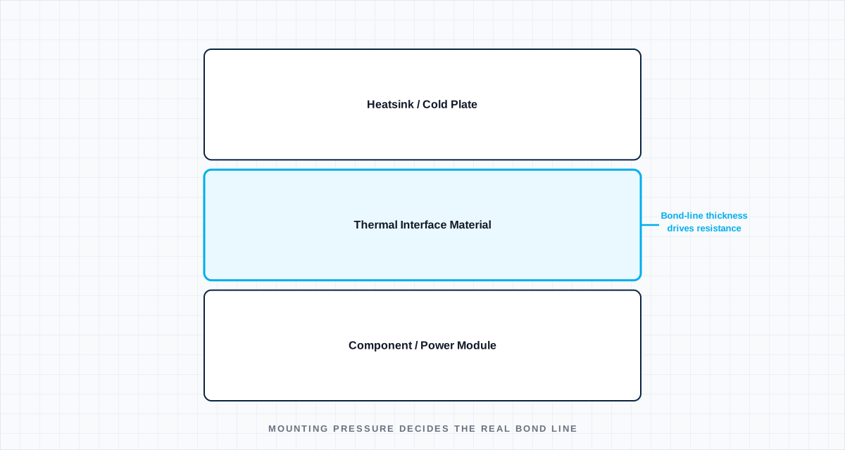
Datasheets list thermal conductivity under ideal lab conditions: a fixed test pressure, a controlled bond-line thickness, a flat and rigid test fixture. Real assemblies apply uneven mounting pressure across a component with its own flatness tolerance, land on a heatsink with its own machining tolerance, and run at production ambient temperatures the lab test never simulated. The gap between that number and what a thermal interface material (TIM) actually delivers in an assembled unit is where a surprising number of "the design should have enough thermal margin" assumptions quietlrials.svg)
How mounting pressure changes effective thermal resistance
Every TIM's thermal resistance is a function of the actual bond-line thickness it settles to under real mounting pressure, not the thickness assumed on the datasheet. Under-torqued fasteners, warped heatsinks, or a PCB assembly with more flex than the mechanical design accounted for all increase the effective bond line beyond what the material's rated thermal conductivity assumed — and because thermal resistance scales with bond-line thickness, a TIM that looks like it has generous margin on paper can end up running close to its limit once real mounting variance is in the loop.
This is compounded in production by fastener torque variance across an assembly line, which the bench-built engineering sample — torqued carefully, by hand, by someone paying close attention — never experiences. A thermal validation done once, on a hand-assembled unit, describes best-case bond-line thickness, not the distribution of bond-line thickness a production run will actually produce.
Gap pad vs. grease vs. phase-change: when each one actually wins
Gap pads win when mechanical tolerance stack-up is large and needs to be absorbed without adding a separate compliant layer — they're forgiving of uneven surfaces and inconsistent assembly pressure, at the cost of generally higher thermal resistance than grease for the same bond-line thickness. Thermal grease wins when the mating surfaces are flat, rigid and the gap is small and consistent — it delivers the lowest thermal resistance of the common options, but that performance is highly sensitive to applied pressure and is difficult to inspect after assembly, which makes it a poor choice when process control on mounting pressure isn't tight. Phase-change materials sit between the two: solid and easy to handle at room temperature for consistent placement during assembly, then transitioning to a low-viscosity, grease-like state at operating temperature to fill microscopic surface irregularities — a reasonable default when both mechanical inconsistency and assembly-process simplicity matter more than squeezing out the last fraction of thermal performance.
The choice that actually matters isn't which material has the best thermal conductivity number — it's which failure mode the application can least tolerate: a thermal budget too tight to absorb grease's pressure sensitivity, or a mechanical tolerance stack-up too loose to trust a rigid gap pad's assumed compression.
Why the datasheet's "typical" number is rarely what you'll see in production
A datasheet's "typical" thermal conductivity value is measured under the material supplier's own idealized test conditions, and it describes the material's ceiling, not what a given application's actual mounting pressure, bond-line thickness and surface flatness will deliver. The number worth designing to is the material's performance at the specific pressure and bond-line thickness the actual mechanical stack-up will produce — available from the supplier's pressure-vs-thermal-resistance curve, not the single number in the marketing table — combined with the tolerance range that thickness will fall across in production, not just at nominal.
Skipping that step is how a thermal design that "passed" on a bench unit, assembled with more care and more consistent pressure than a production line will apply, ends up with less real margin than the validation report implied.
Define the boundary
Name the operating state, interfaces, tolerances and degraded conditions. A test without a boundary only proves the sample survived once.
Capture the right signal
Choose measurements fast and close enough to the mechanism to explain cause, sequence and margin—not just the final alarm.
Set a decision rule
Agree before the test what passes, what triggers redesign and what uncertainty requires another experiment.
Turn the lesson into a validation plan.
Bring us the requirement, failure signature or architecture boundary. We will help frame the evidence needed to make the next decision.