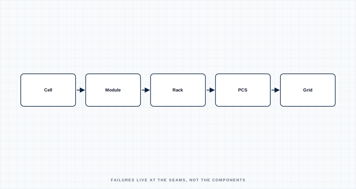
A battery cell datasheet is the easiest part of a BESS project to get right. Cycle life, capacity, internal resistance, temperature curves — all of it is measured, published, and comparable across suppliers. The problems that actually delay a grid-scale battery energy storage system (BESS) project almost never come from the cell itself. They come from the seams: cell to module, module to rack, rack to PCS, PCS to grid, and grid to dispatch. This is a field-level walk through where those seams tend to open up, from initial cell qualificationcell-to-commissioning.svg)
Cell and module qualification: the variance problem
Every LFP cell qualification report looks clean because it's built from a sample batch under controlled conditions. The real question for a multi-MWh project isn't "what does this cell do," it's "how much does cell-to-cell variance grow across a production run of tens of thousands of units, and how does that variance propagate through the module and rack architecture."
Three things matter more than the headline spec:
- Internal resistance spread within a production lot. A module built from cells with a 3% IR spread balances current very differently than one built from cells with a 1% spread, even if the average IR is identical on both datasheets. Wider spread means some cells work harder than others every cycle, and that difference compounds over years.
- Capacity fade correlation across a rack. If cells fade at different rates, the BMS has to manage an increasingly heterogeneous pack, and effective usable capacity of the rack drops faster than any single cell's fade curve would suggest.
- Traceability back to the actual production batch, not just the part number. Two "identical" cell orders six months apart can come from different production lines with meaningfully different characteristics. This matters enormously when a project needs replacement modules three years into a 15-20 year asset life.
None of this shows up on a standard datasheet. It shows up in acceptance testing, and it's the reason acceptance test plans for BESS cells should specify statistical sampling requirements, not just pass/fail thresholds on a handful of units.
BMS calibration: SOC and SOH drift in the field
A battery management system's state-of-charge (SOC) estimate is a model, not a measurement. It's calibrated in the lab against known conditions and then has to hold up against years of real-world temperature swings, partial cycling, and calendar aging. Two failure patterns show up repeatedly in the field:
SOC drift under partial-cycle operation. Grid-scale storage rarely does clean 0-100% cycles — it's constantly doing partial charge/discharge for frequency regulation or peak shaving. Coulomb-counting SOC estimates drift without full-cycle recalibration points, and if the dispatch strategy never takes the pack through a full cycle, that drift compounds silently until state-of-health (SOH) reporting becomes unreliable exactly when the asset owner needs it most — during warranty and performance-guarantee disputes.
SOH definitions that don't match the performance guarantee. A BMS vendor's SOH calculation and the capacity guarantee in the EPC contract are sometimes not measuring the same thing. Getting the BMS's SOH algorithm, its recalibration triggers, and the contractual performance test procedure aligned before commissioning avoids a very unpleasant conversation two years into operation.
Thermal design at the container level
Cell-level thermal management is well understood. What's harder is container-level thermal design when you're stacking dozens of racks in a confined enclosure with genuine fire-safety consequences if it's wrong.
The recurring issue is airflow (or coolant flow, in liquid-cooled systems) uniformity across racks that are physically identical but positioned differently relative to the HVAC or cooling loop inlet. Racks near the inlet run cooler; racks at the far end run warmer under the same load, age faster, and become the weak point in the system years before the design life would predict. This is a CFD problem that needs to be solved at the container layout stage, not discovered during summer peak operation.
Thermal runaway propagation testing deserves the same attention. A cell that goes into thermal runaway inside a module should not propagate to the adjacent module — that's the entire point of module-level containment design — but propagation testing is expensive and sometimes gets scoped down to "cell-level testing only" under budget pressure. For any project targeting bankability with an insurer or an offtake counterparty, container-level propagation testing (not just cell-level) is usually a hard requirement, and it's far cheaper to plan for it than to retrofit after an insurer asks for it during financial close.
PCS and grid interconnection: where dispatch tests get real
The power conversion system (PCS) is where a BESS project meets the actual grid code, and this is where a lot of schedule risk hides.
Anti-islanding and ride-through behavior have to be validated against the specific grid code of the interconnection point, not a generic IEEE 1547 or IEC 62477 baseline. Grid codes vary meaningfully between utilities and countries on voltage ride-through windows, frequency ride-through, and reactive power support requirements during disturbances. A PCS pre-configured for one grid code's default parameters will fail interconnection testing against a different one, and reconfiguring firmware parameters under commissioning time pressure is a common source of schedule slip.
Harmonics and power quality under partial-load and partial-SOC operation is a different test condition than the full-load, full-SOC test most PCS units are characterized against in the factory. Total harmonic distortion (THD) at 20% state of charge and 30% load — a realistic operating point for frequency regulation duty — is not the same as THD at the nameplate test point, and utility power quality requirements don't care which condition is more convenient to test.
Multi-vendor synchronization, where the BMS, PCS, and site-level energy management system (EMS) come from different suppliers, is where communication protocol mismatches surface — Modbus register maps that don't match documentation, DNP3 point mapping errors, or timing assumptions that work in each vendor's isolated test environment but create race conditions once integrated. This is the single most common cause of commissioning delay on multi-vendor BESS projects, and it's almost entirely avoidable with a documented interface control document (ICD) agreed by all three parties before equipment ships.
EMS/SCADA integration and dispatch testing
Getting a site to "power on" is not the same as getting it to "dispatch correctly." Dispatch testing needs to validate the system across the actual operating envelope it will see in production — not just full charge and full discharge, but ramp-rate compliance during frequency events, response time to automatic generation control (AGC) signals, and correct behavior when SOC limits and power limits conflict (which they will, regularly, in real operation).
The projects that commission smoothly are the ones where dispatch test procedures were written and agreed with the offtaker or grid operator before the equipment arrived on site — not improvised during a commissioning window that's already under schedule pressure with liquidated damages accruing.
The pattern across all of this
Every issue above shares a common root cause: individual components perform exactly as specified, and the system still doesn't behave as expected, because the interfaces between components were under-specified relative to how the system is actually operated. Datasheets describe components in isolation. Grid-scale BESS performance is determined at the integration boundaries — and that's where engineering attention needs to go earliest, not latest.
Define the boundary
Name the operating state, interfaces, tolerances and degraded conditions. A test without a boundary only proves the sample survived once.
Capture the right signal
Choose measurements fast and close enough to the mechanism to explain cause, sequence and margin—not just the final alarm.
Set a decision rule
Agree before the test what passes, what triggers redesign and what uncertainty requires another experiment.
Turn the lesson into a validation plan.
Bring us the requirement, failure signature or architecture boundary. We will help frame the evidence needed to make the next decision.