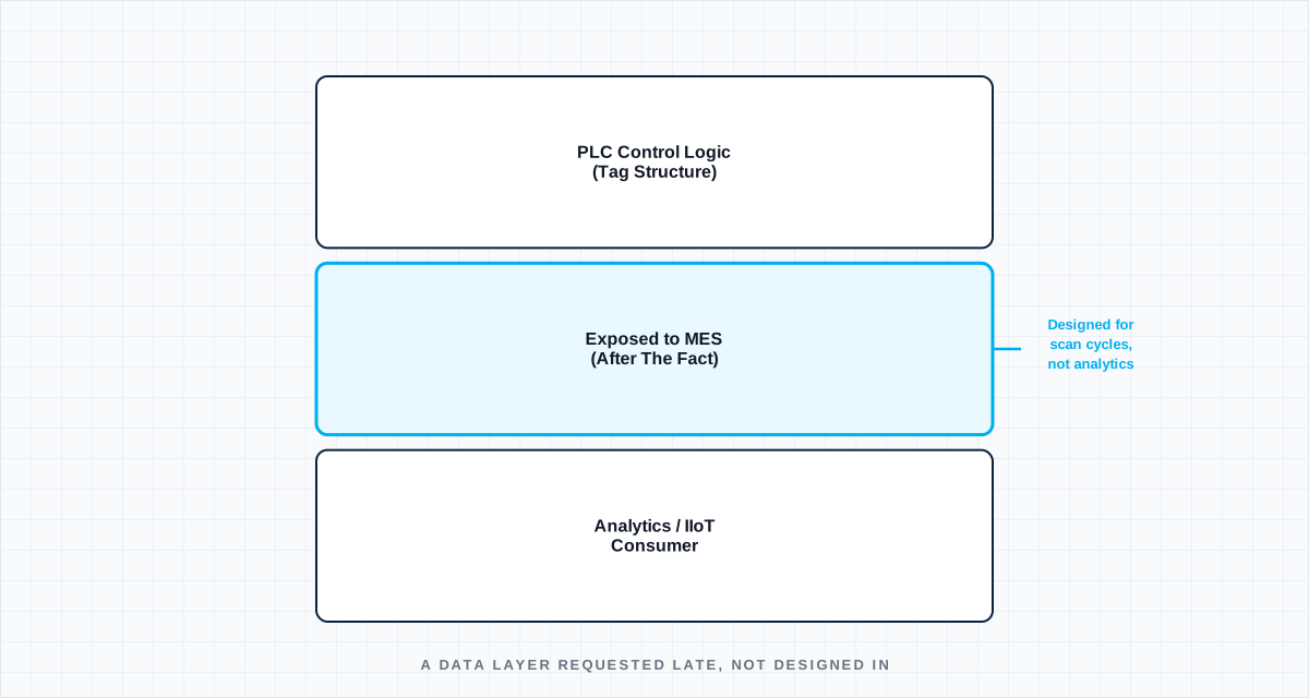
Ask most automation teams when the IIoT and MES data layer got designed, and the honest answer is usually that it didn't — it got added, after the PLC program architecture was already finished, as a set of tags someone exposed because a data or analytics request came in late in the program. That ordering, not any specific technical mistake, is the root cause of most of the IIoT integration pain that shows up later: a data layer that was never a first-class design input ends up structurally constrained by decisions that were made without it ingned.svg)
Tags designed for control logic aren't designed for analytics
A PLC program's internal tag structure gets organized around what the control logic needs to reference efficiently — scan-cycle-friendly data types, internal state that only makes sense in the context of the rung logic that produced it, update rates tuned to control-loop timing, not reporting timing. When that same tag structure gets exposed wholesale to an MES or analytics layer after the fact, the analytics team inherits a data model that was never meant to be read by anything other than the control program itself — internal states with no documented meaning outside the ladder logic, timestamps at control-loop resolution when a much lower rate would have served analytics better, and no consistent naming convention because none was ever needed when the only consumer was the PLC itself.
Polling rate is a request, not a network property
When data requirements get bolted on late, the request usually comes in as a data rate — "we need this tag every 100 milliseconds" — without anyone checking whether the network segment carrying that tag, already provisioned for the control and safety traffic it was actually designed around, has headroom for that additional polling load. On an isolated cell tested standalone, the extra polling traffic is invisible. Once every cell on the line is live simultaneously, cumulative IIoT polling traffic competing with control-loop and safety traffic on a shared industrial network is one of the most common places integration problems concentrate — and because the symptom looks like general network congestion, it frequently gets diagnosed as a hardware or network equipment issue rather than what it actually is: a data layer that consumed bandwidth nobody budgeted for it.
Designing the data layer as a requirement, not a request
The fix is treating IIoT and MES connectivity as a stated requirement at PLC program architecture time — what data does downstream analytics actually need, at what rate, and what's the tag structure and naming convention that will make sense to a system other than the control program that originally produced it — locked in alongside the control logic design, not requested from it afterward. A data layer designed this way costs a small amount of extra coordination early in the program. A data layer added afterward costs a control-program rework, a network capacity problem discovered during commissioning, or both — usually on a schedule that has much less room to absorb it.
Define the boundary
Name the operating state, interfaces, tolerances and degraded conditions. A test without a boundary only proves the sample survived once.
Capture the right signal
Choose measurements fast and close enough to the mechanism to explain cause, sequence and margin—not just the final alarm.
Set a decision rule
Agree before the test what passes, what triggers redesign and what uncertainty requires another experiment.
Turn the lesson into a validation plan.
Bring us the requirement, failure signature or architecture boundary. We will help frame the evidence needed to make the next decision.