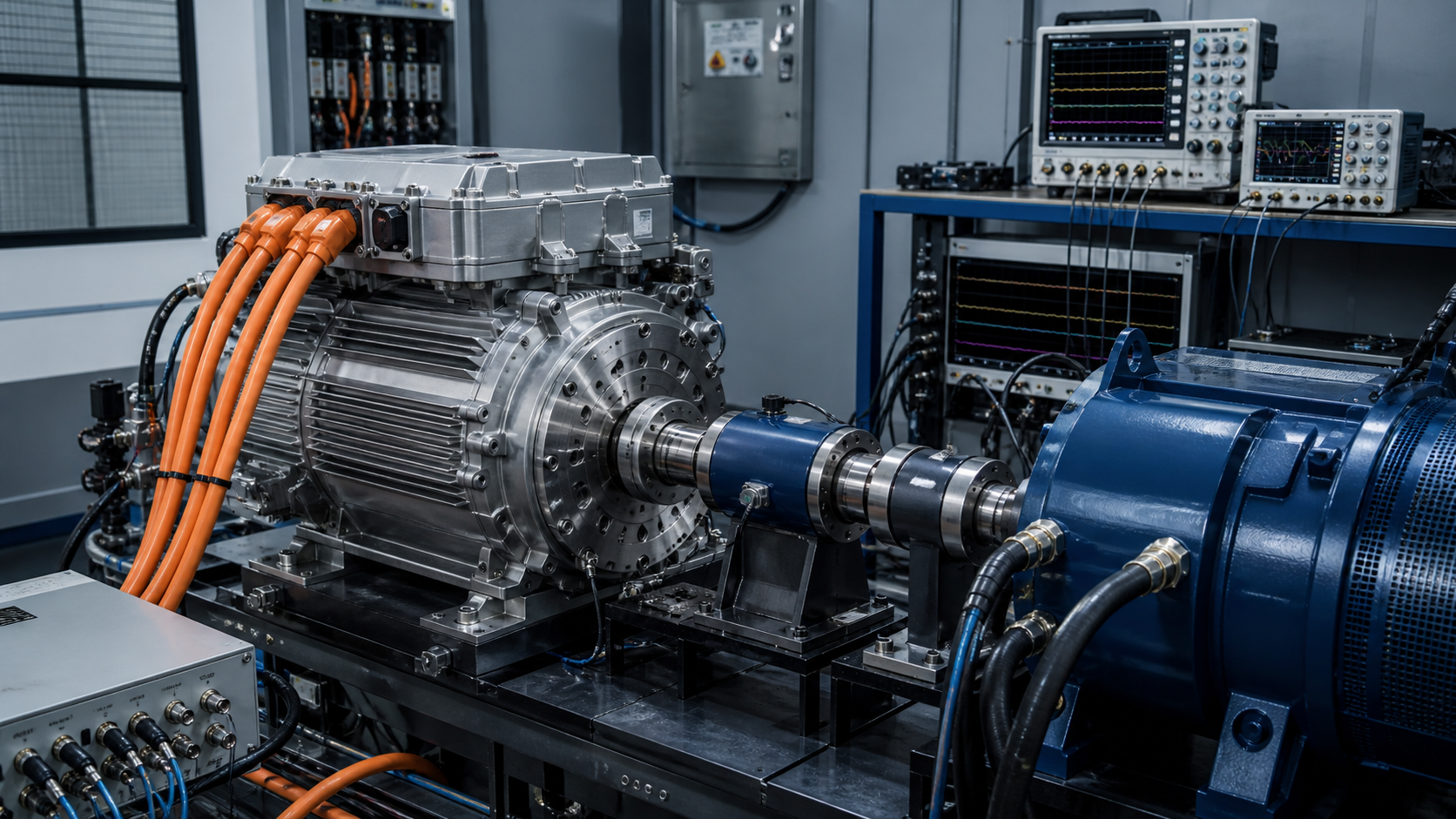
Motor-control problems rarely announce themselves as “the current loop is unstable.” They arrive as a buzz at one speed, torque ripple under light load, an overcurrent during regeneration, poor launch feel, or a fault that appears only with a warm motor and low battery voltage. The symptom is mechanical or vehicle-level; the mechanism often begins in timing, estimation or saturation inside the inverter.
Start with the timing chain
Field-oriented control assumes that current samples describe the phase currents associated with a known rotor angle and a known PWM state. ADC aperture, PWM synchronization, signal filtering, software execution, position-sensor latency and gate-command update all contribute phase delay. More bandwidth is not automatically better: once delay consumes phase margin, aggressive gains amplify noise and cross-coupling.
Document the chain in microseconds, not task names. Measure sample-to-actuation latency and jitter on hardware. Confirm whether current is sampled away from switching edges across the full modulation range. At high modulation index, valid sampling windows shrink; reconstruction logic that works at medium speed may become the failure mechanism near voltage saturation.
Parameters do not stay nominal
Stator resistance changes strongly with temperature. Inductance changes with current and magnetic saturation. Magnet flux varies with temperature and manufacturing spread. DC-link voltage moves with battery state, cable impedance and load transients. A controller calibrated around nominal parameters can lose decoupling accuracy and observer margin at the corners.
Build a parameter envelope and test combinations, not isolated extremes. Hot motor plus low DC-link voltage plus high requested torque is more revealing than three separate tests. Include inverter dead time, device voltage drop and current-sensor offset because low-torque behavior is dominated by nonidealities that disappear at high current.
Torque ripple is a spectrum, not one number
Separate electrical-order content from mechanical resonances. Examine torque or acceleration spectra against electrical frequency, mechanical order, PWM carrier and control update rate. A peak that tracks electrical speed points toward harmonics, angle error or current distortion. A peak fixed in physical frequency may indicate a driveline or mounting mode being excited by otherwise modest torque ripple.
Avoid solving every noise complaint with a notch filter. A notch can hide a resonance while adding delay or creating a new calibration dependency. First identify the excitation source, then decide whether to reduce the source, move the structural mode, or add targeted damping.
Saturation and transitions are where production faults live
Validate torque sign changes, field weakening, maximum torque per ampere transitions, regeneration limits and current-vector saturation explicitly. Integrator windup during voltage saturation can turn a recoverable transient into an overcurrent. Arbitration between traction control, battery limits, thermal derating and driver demand must be deterministic and rate-limited where the mechanical system requires it.
Evidence for release
A release package should include loop frequency response or equivalent margin evidence, latency and jitter measurements, parameter-envelope tests, current reconstruction coverage, spectral analysis of torque ripple and transition tests at voltage and temperature corners. Vehicle testing then verifies interaction with the real driveline; it should not be the first place fundamental loop stability is assessed.
Define the boundary
Name the operating state, interfaces, tolerances and degraded conditions. A test without a boundary only proves the sample survived once.
Capture the right signal
Choose measurements fast and close enough to the mechanism to explain cause, sequence and margin—not just the final alarm.
Set a decision rule
Agree before the test what passes, what triggers redesign and what uncertainty requires another experiment.
Turn the lesson into a validation plan.
Bring us the requirement, failure signature or architecture boundary. We will help frame the evidence needed to make the next decision.