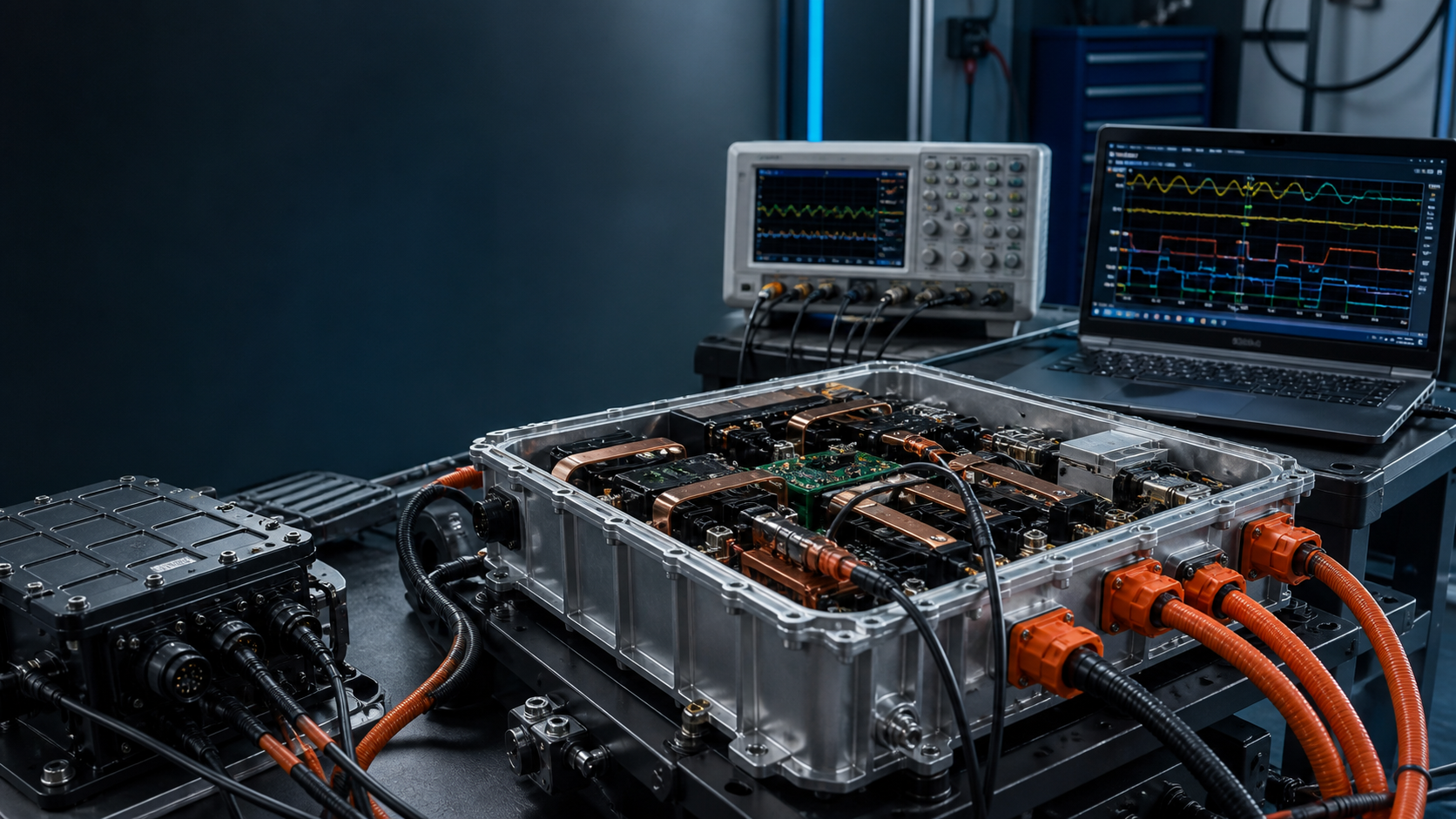
Combining traction inverter, power distribution, onboard charger, high-voltage DC-DC, low-voltage DC-DC and auxiliary functions can reduce connectors, harness mass and enclosure cost. It also removes the physical separation that previously contained faults and interference. The hardest 6-in-1 problems are not six independent converter designs. They are the electrical, thermal, mechanical and diagnostic resources those converters now share.
DC-link ownership
The traction inverter produces large, fast current transients. The OBC presents grid-facing control requirements. DC-DC stages can excite impedance interactions. Shared capacitors and busbars reduce duplication but create a coupled impedance network. Analyze source and load impedance across frequency and across operating modes; a converter stable against an ideal supply may oscillate when connected through another converter's input filter.
Pre-charge is also a system sequence. Define which capacitors are charged, which contactors close, how weld detection works, what happens after an interrupted sequence and how stored energy is discharged. The PDU cannot be reviewed as copper and contactors alone; its state machine is part of every converter's safe startup.
Common-mode current finds the shared enclosure
Fast inverter switching drives common-mode current through motor capacitance, shields, bearings, coolant paths and chassis. OBC filters connect to the charging interface and protective earth. When these functions share a housing, parasitic capacitance can create paths that were absent in separate boxes. A filter that passes in an isolated subsystem test may fail when the complete assembly changes the return network.
Build a high-frequency equivalent model of switching nodes, baseplate, coolant, connector shields and chassis bonds. Control the geometry of the return path. “Ground” is not a node at these frequencies; it is an impedance distributed through metal, fasteners and cable shields.
Thermal coupling changes derating
Peak traction, fast charging and cabin or auxiliary loads may not occur simultaneously in a requirement table, yet hot-soak and transition states can overlap their thermal histories. Shared coolant improves packaging but means pressure drop, flow allocation and inlet ordering determine which function receives thermal margin.
Derating should use junction estimates and actual coolant conditions, not one enclosure temperature. Test blocked or degraded flow, pump variation, trapped air and sensor offset. Define whether a hot OBC may constrain traction immediately after charging and whether that behavior is visible to the vehicle controller and driver.
Isolation and fault containment
A single insulation-monitoring value does not identify the failing branch. Provide a diagnostic strategy that can isolate sections or infer likely paths without unsafe service procedures. Review creepage and clearance after tolerance, contamination and assembly movement. Consider whether a failure in low-voltage auxiliary power can disable the contactor, cooling or logging needed to manage a high-voltage fault.
Integration exit criteria
Release requires mode-transition testing across drive, regenerate, charge, sleep and wake; impedance and transient evidence for the shared bus; complete-assembly EMC; thermal testing with realistic prior-state history; and fault injection across shared supplies, communications, cooling and isolation. If validation is only the sum of six supplier test reports, the integrated product has not been validated.
Define the boundary
Name the operating state, interfaces, tolerances and degraded conditions. A test without a boundary only proves the sample survived once.
Capture the right signal
Choose measurements fast and close enough to the mechanism to explain cause, sequence and margin—not just the final alarm.
Set a decision rule
Agree before the test what passes, what triggers redesign and what uncertainty requires another experiment.
Turn the lesson into a validation plan.
Bring us the requirement, failure signature or architecture boundary. We will help frame the evidence needed to make the next decision.